ASE A8 Engine Performance Practice Test

Diagram of an automotive MAP sensor's circuit.

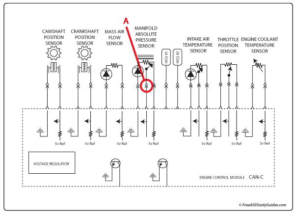
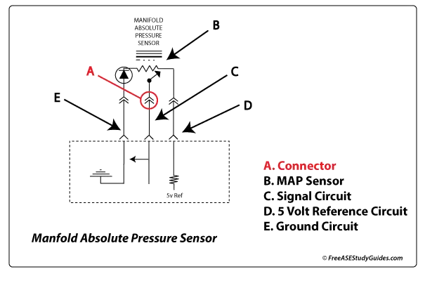
29. Component A in the diagram above is:

  • A. A connection in the signal circuit of the MAP sensor.
  • B. A splice in the signal circuit of the MAP sensor.
  • C. A splice in the ground circuit of the MAP sensor.
  • D. A connection in the reference circuit of the MAP sensor.

29.

MAP sensor circuit

Answer A is correct. This is the connector for the signal circuit of a MAP sensor.

Answer B is wrong. A splice is a solid black dot connecting two wires.

Answer C is wrong. The symbol for a connector is circled in red. It's part of the signal circuit for the manifold absolute pressure sensor.

Answer D is wrong. The reference voltage circuit is labeled 5V ref.