Transmission Hydraulic Flow
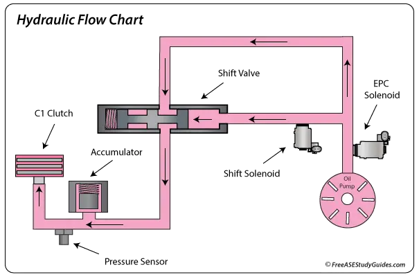
Automatic transmissions use mainline, governor, and throttle pressure to control flow and lubricate the transmission. The governor and modulator found in hydraulic transmissions have been replaced or work together with electronics.
Governor Pressure
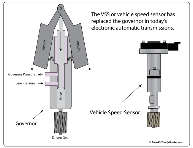
Governor pressure increases with vehicle speed. Older transmissions had mechanical governors that consisted of springs, centrifugal weights, and a spool valve to control this pressure. Electronic transmissions use the vehicle speed sensor signal for vehicle speed. Governor pressure causes a transmission to upshift, and throttle pressure causes it to downshift. Governor pressure works on one end of the valve, and a spring assisted by throttle pressure works on the other.
Throttle Pressure
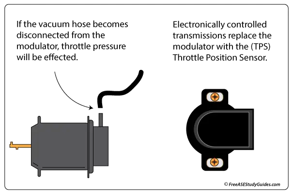
Throttle pressure indicates engine load. Older transmissions use a vacuum modulator or throttle linkage to control the throttle valve. Late-model vehicles use electronic sensors and electric solenoids to achieve the same results.
Shift Valves
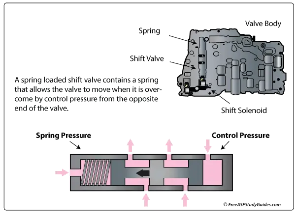
Shift valves control hydraulic flow to the reactionary devices (clutches and bands) that drive and hold members of the planetary gear set. Transmissions change gears by moving shift valves.
When a vehicle first accelerates from a stop, throttle pressure is higher than governor pressure, so it stays in first gear. As speed increases, the governor pressure (affected by vehicle speed) increases until it overcomes throttle pressure, moves the shift valve, and causes an upshift.
When throttle pressure overcomes governor pressure, the transmission downshifts. When a driver accelerates to pass another vehicle, there's an increase in throttle pressure, causing a downshift. These two pressures control shift valve movement.