Throttle Position Sensor
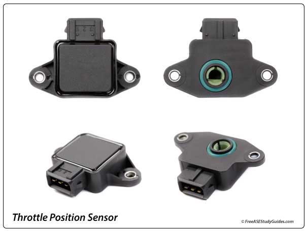
The Throttle Position (TP) sensor is located on the throttle body of a fuel-injected engine. This type of sensor is known as a potentiometer, a variable resistor used to control voltage in a circuit. The TP sensor is used to detect engine load. The PCM and the TCM share the output. This sensor's signal and vehicle speed sensor are used by the TCM to provide optimal shift timing.
Most TP sensors have extra pins for extra internal functionality. For this discussion, we look at three terminals and the sensor's connection to the automatic transmission. A faulty TP sensor causes erratic shift timing and affects torque converter engagement.
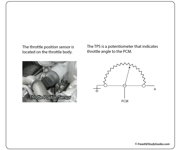
One lead directly connects to the computer's 5-volt reference voltage supply. The opposite end of this internal resistance strip is the ground. Another is connected to the PCM. This wire connects to the movable arm that swipes across an internal resistance strip, sending a varying voltage signal back to the PCM. This signal indicates the engine's throttle angle. It sends a varying voltage signal to the controller, indicating the throttle angle changes.
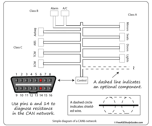
The sensor is attached to the throttle plate shaft and changes output voltage as the throttle plate opens and closes. The output voltage will be low or around 0.45 volts if the throttle is closed and will be high or 4.5 volts at (WOT) Wide Open Throttle. The PCM adjusts the fuel injection and ignition timing as the throttle plate moves. If the driver suddenly accelerates their vehicle, the PCM receives this 4.5-volt signal, increasing the fuel injection time to compensate. The TCM receives the signal over the CAN and initiates a downshift.