Electric Cooling Fan Circuit
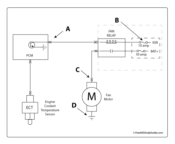
Today's electric engine cooling fans are computer-controlled. The control module uses a signal from the ECT or engine coolant temperature sensor to operate the fan motor. Notice in the illustration that the driver grounds the fan relay circuit to operate the fan motor.
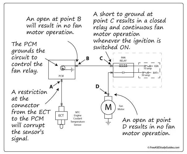
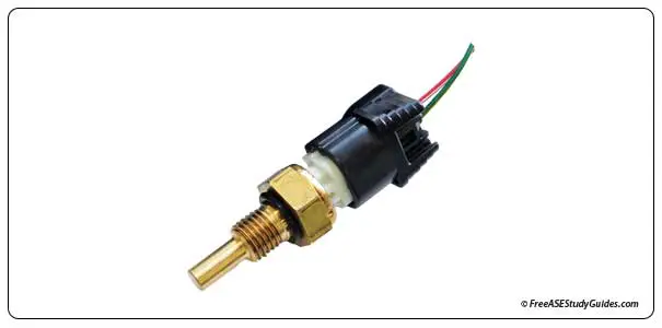
Point A points toward the connector from the ECT sensor to the control module. Any resistance in this circuit corrupts the signal, affecting fan motor operation.
Like the other points, Point B points at a connector. An open in the circuit caused by a broken wire or a loose plug or pin would result in no fan operation. The circuit driver cannot ground the circuit controlling the fan motor relay.
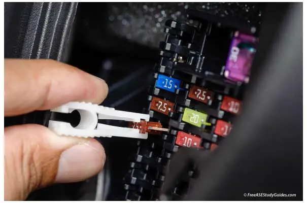
A short to ground at point C causes the relay to close, activating the fan motor whenever the ignition switch is turned or pushed ON. Short circuits cause high currents, burning the circuit's fuse.

An open at point D, the connector leading to the fan motor, results in no fan motor operation — all four answers point to connectors. Connectors and plugs are a common source of problems in electrical circuits. If suspected, they should be visually inspected and tested for continuity and voltage drop.