Oscilloscope Waveforms
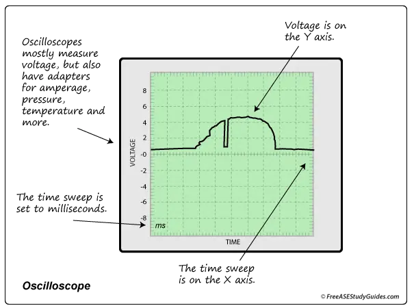
Oscilloscopes display a graph of an electrical signal in a circuit over time. They display real-time signals, allowing us to look at the behavior of a circuit. They are ideal for diagnosing automotive circuits like ignition systems and today's computer modules and sensors.
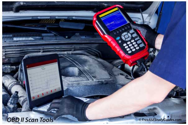
They can be a standalone unit, inside a scan tool, PC software, or combined with a multimeter. A handheld scope typically contains an oscilloscope and a multimeter. To test a circuit, connect the ground probe to a good ground and the test probe to the signal circuit. Try to probe close to the device.
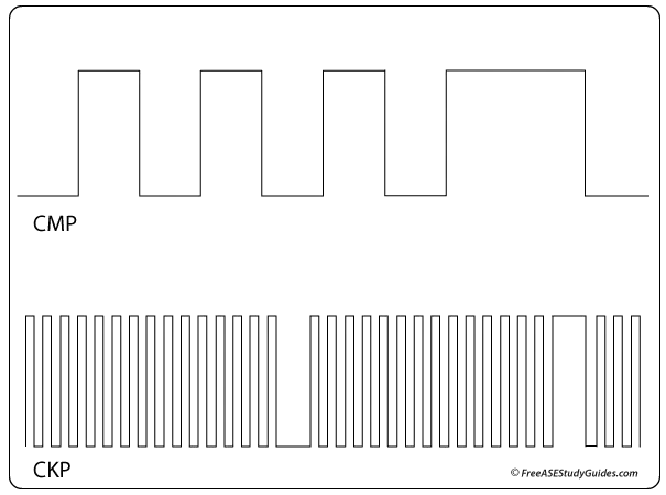
The camshaft and crankshaft waveforms above can be displayed simultaneously with a dual-trace oscilloscope. Waveforms can be paraded and stacked for easy comparison. This function is excellent for diagnosing ignition systems. Look for inconsistencies like high or low lines in the waveform. Once a waveform is displayed, it can be compared to a known good pattern. These known good patterns are often stored in our scan tools or found online with a simple search.
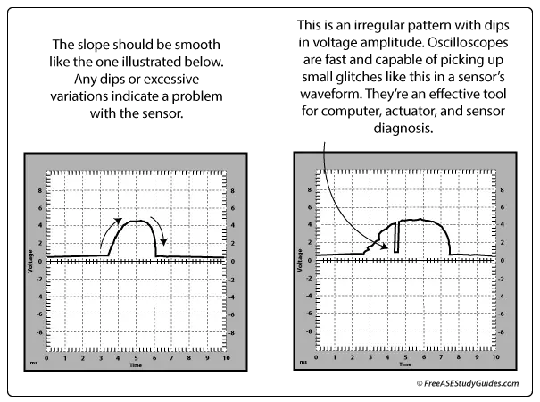
Light dimmer switches and potentiometers, like the throttle position sensor in the image, should have a smooth sloping pattern. Probe the signal wire from the TPS to display its waveform. The TPS on the right has skips and dips in its pattern as the throttle plate is opened and closed. This skip results in hesitation while accelerating. Oscilloscopes can be handy. It quickly identified the TP sensor as faulty. Adapters are available to display different waveforms like temperature, pressure, and current.