Block Diagrams
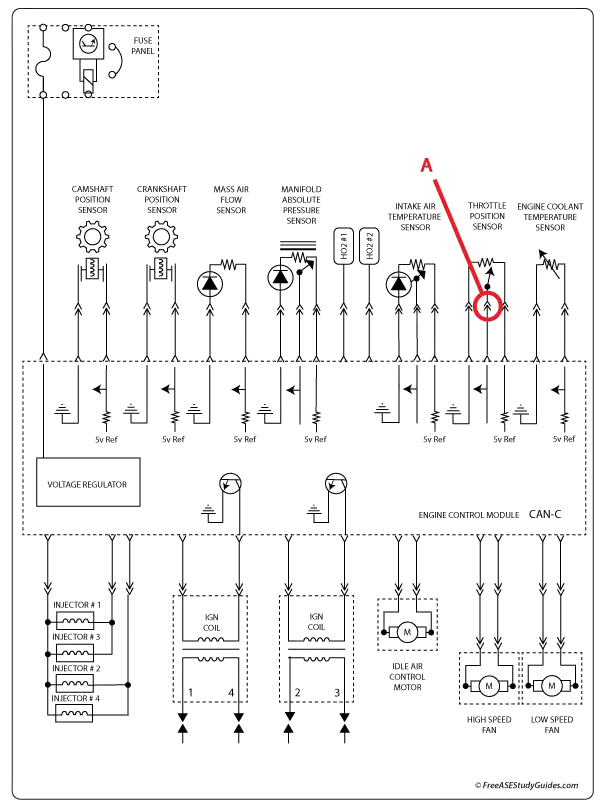
This is a diagram of a (PCM) Powertrain Control Module. Vehicle manufacturers create diagrams of the entire vehicle that can be complex and difficult to sort through, so they're broken down into system-specific diagrams called block diagrams. Wiring diagrams show the wiring, connectors, and other system-related information. They're like road maps for the wiring routed throughout a vehicle.
The diagram above has several different schematic symbols. Schematics are used in electronics; they contain standardized symbols to represent components in a circuit. The diagram above contains diodes, resistors, variable resistors, and other symbols representing solid-state circuitry. Component A is a connector. Notice the black dots; they represent a splice or junction where wires are connected. When wires in a schematic cross without a dot, they are not connected.