Schematic Diagrams
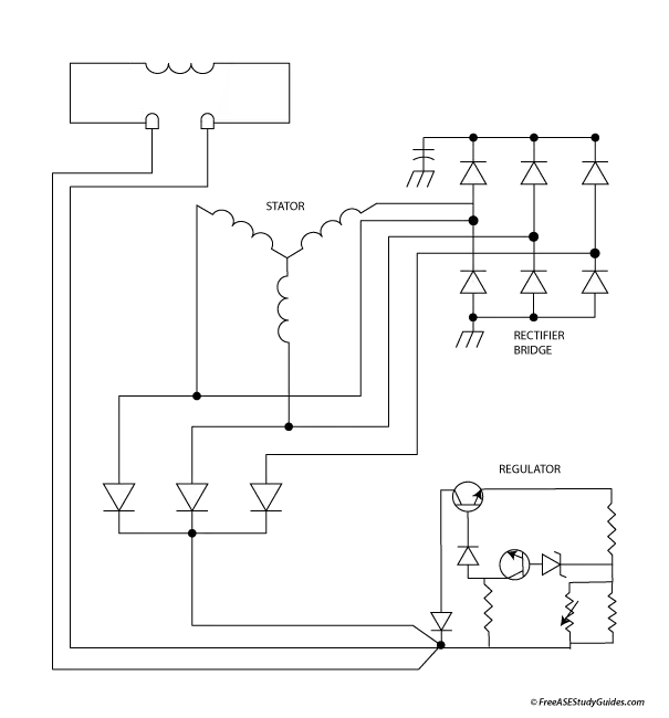
Vehicle manufacturers create diagrams of the entire vehicle that can be complex and difficult to sort through, so they're broken down into system-specific diagrams called block diagrams. Wiring diagrams show the wiring, connectors, and other system-related information. They're like road maps for the wiring routed throughout a vehicle. The diagram above is a schematic.
Notice the black dots; they represent a splice or junction where wires are connected. When wires in a schematic cross without a dot, they are not connected.
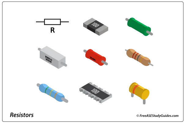
Schematics are used in electronics; they contain standardized symbols to represent components in a circuit. The schematic above contains diodes, resistors, a variable resistor, and symbols representing solid-state circuitry.
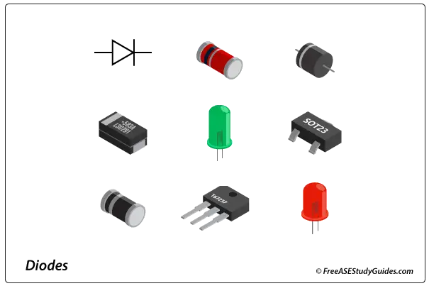
Diodes are simple semiconductors that allow current to flow only in one direction by joining one material for the negative side to another different material for the positive side. The negative side of a diode is called the cathode, and the positive side is called the anode.