Brake Light Circuits
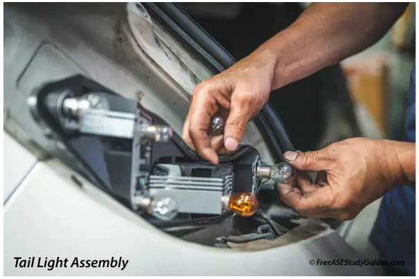
Brake lights are wired in a parallel circuit because one bulb or socket can fail, and the others will still illuminate and function normally.
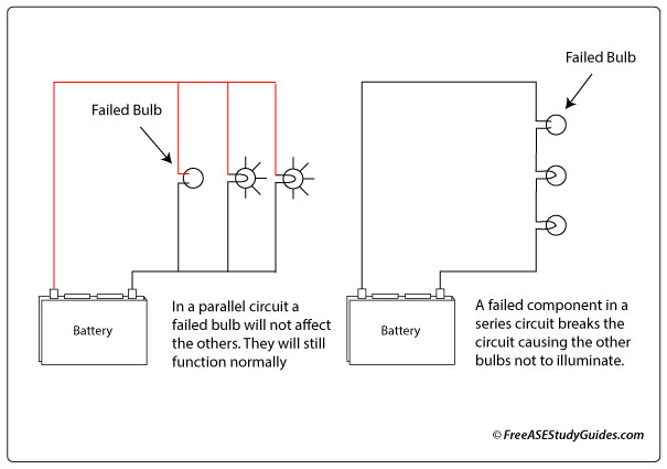
If one bulb is burned out in a brake circuit, it is likely associated with the individual bulb or the socket. A series circuit is different. Components are daisy chained and when one bulb fails, the other bulbs are rendered inoperable. In a parallel circuit the voltage remains the same and the current is divided among the bulbs. In a series circuit current remains the same and voltage is divided among the bulbs.
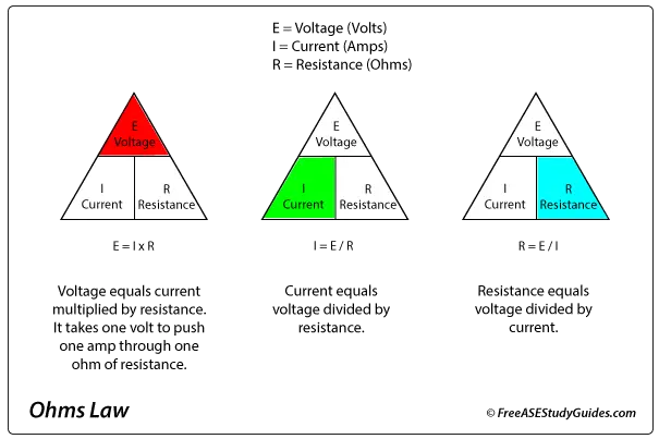
Remember Ohm's Law (I=V/R) whenever working with automotive circuits. Be careful and check specifications before adding additional items to a factory system. Adding items lowers resistance and increases the current (amperage). This additional current can damage components and burn sensitive wiring.