ASE A8 Engine Performance Practice Test

Diagram of automotive ECM engine control system.

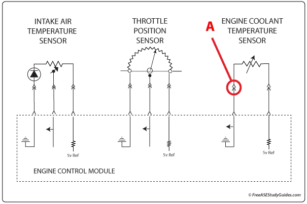
21. An ohmmeter indicates excessive resistance at point A in the schematic diagram above. All of the following statements are true about this circuit EXCEPT:

  • A. Point A is the ground connection for an (NTC) negative temperature coefficient sensor.
  • B. Too much resistance at point A will delay torque converter lockup-clutch engagement.
  • C. Too much resistance at point A will affect the air-fuel ratio.
  • D. Too much resistance at point A will result in continuous engine cooling fan operation.

21.

Answer A is wrong. Point A is the ground connection in the connector for the Engine Coolant Temperature Sensor, an (NTC) negative temperature coefficient sensor. With an NTC sensor, resistance decreases as temperature increases.

Answer B is wrong. The ECT sensor affects several different systems. For example, the ECM adjusts the EGR flow, the air-fuel mixture, delays the torque converter lock-up clutch, or A/C compressor engagement according to engine temperature.

Answer C is wrong. The ECM runs a startup strategy that enriches the air-fuel ratio when the engine's coolant is cold. The extra resistance added to the circuit results in a rich air-fuel ratio.

Answer D is correct. This is an EXCEPT-type question. The ECM uses different strategies programmed into its lookup tables for hot and cold operating conditions. Too much resistance at point A will result in a corrupt signal and delayed engine cooling fan operation.