Steering Angle Sensor
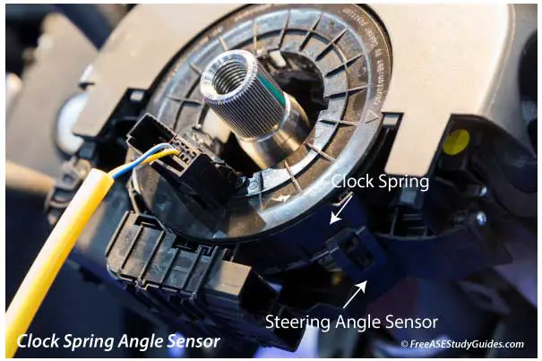
The SAS, or steering angle sensor, is attached to the steering column and measures the angle and rotation speed of the vehicle's steering wheel.
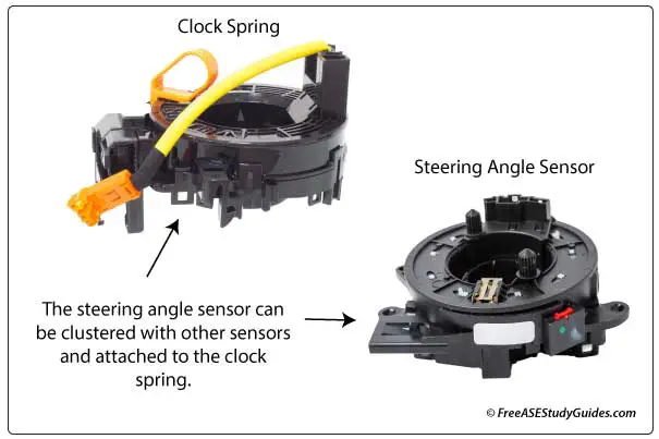
The steering angle sensor may be integral or attached to the clockspring and clustered with other sensors like the torque sensor.
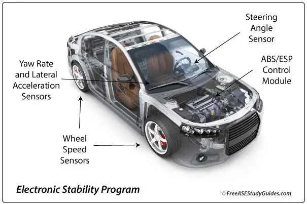
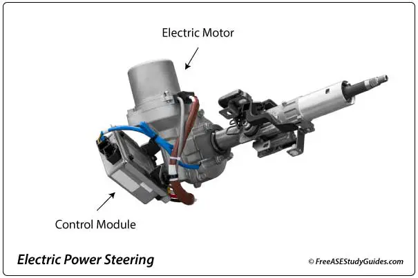
The SAS sensor provides input for the electric power steering, traction control, and advanced driver assistance systems. The control modules sense actual conditions with input from the lateral acceleration, yaw, and vehicle and wheel speed sensors. They compare them to the driver's input from the steering angle and torque sensors.
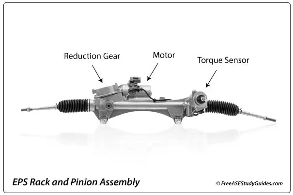
The torque sensor electronically informs the electric power steering, traction control, and advanced driver assistance systems of the force the driver is using to turn the wheel. Torque angle sensors may be located between the steering column and the intermediate shaft and usually come with an alignment tool.
These sensors must be aligned correctly during installation. Use a scan tool with the proper software to reset or calibrate the sensor after the repair.
Power steering motors have great force. Keep hands away from the steering wheel when pressing the ignition button or turning the ignition key after a repair.
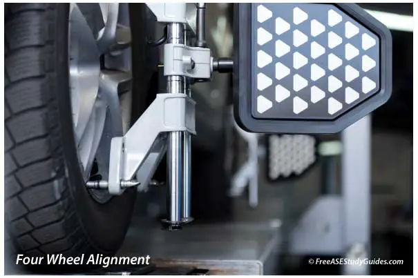
A faulty SAS sensor results in intermittent or loose/tight steering problems. The control module will set fault codes and illuminate the ABS/ESC and EPS warning lights. Modern wheel alignment machines can reset the sensor after an alignment.
SAS and the Controller Area Network
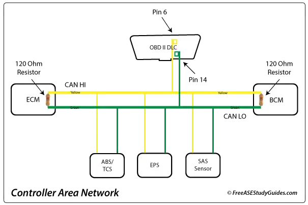
The steering angle sensor may connect to a module like the electric power steering control module or communicate directly on the CAN. The CAN or controller area network is a reliable serial priority-based messaging protocol and the industry standard for high-speed automotive network communications.
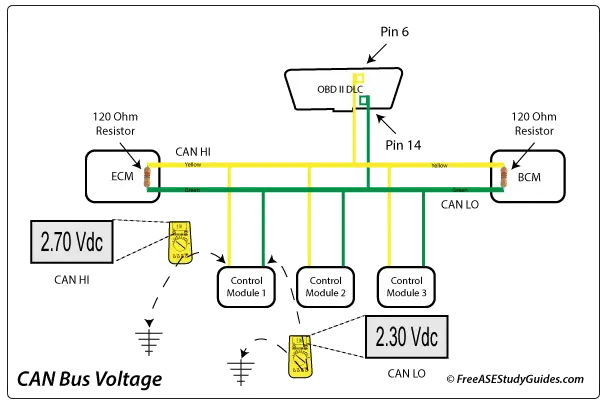
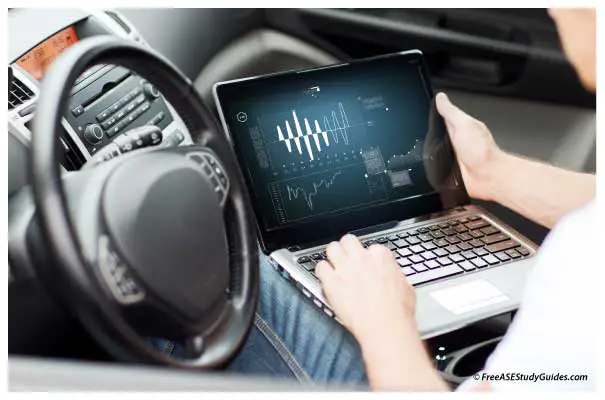
A multimeter can measure the average of all voltage signals on the CAN bus. The reading changes with the activity on the bus. Typically, the measurement is taken from the OBD II DLC of a system without a gateway or by back-probing the CAN HI and CAN LO pins of an easy-to-access control module's connector on a system with a gateway.
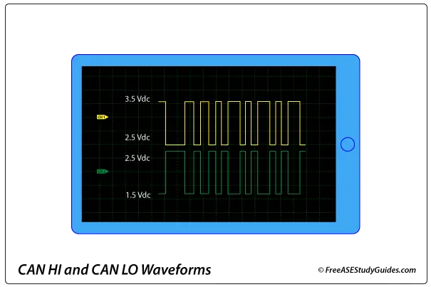
Turning the steering wheel of a modern vehicle with a steering angle sensor will create a voltage signal on the CAN bus. The HI and LO waveforms on the display tend to mirror each other.
SAS Recalibration
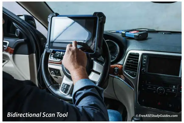
The scan tool displays the angle in degrees, and the sensor is reset or recalibrated after replacing a steering component or performing a wheel alignment. Failure to do so can result in EPS, TCS, check engine warning lights, and problems like erratic or loose/tight steering.
- Some sensors reset automatically during the test drive.
- Some sensors are reset or recalibrated with a scan tool.
- Some manufacturers have a procedure. For example, press the ignition button ON and OFF, or turn the steering wheel from one stop to the other to the center after replacing a part or performing a wheel alignment.