Parking Brake Circuits
Brake systems have switches that input signals from the parking brake, brake light switch, master cylinder fluid level sensor, and ABS accumulator. The control module and instrument panel use these signals to activate actuators and the instrument panel's parking and brake warning lights.
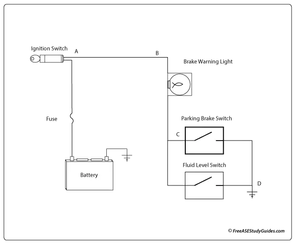
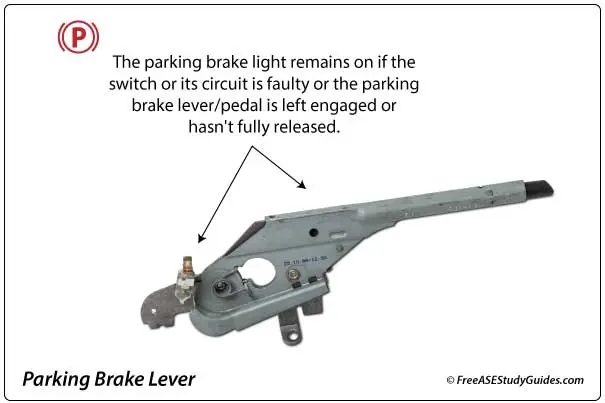
Parking brakes can be manual lever and cable operated or electric. Manual brakes typically have a switch on the pedal or lever that completes a circuit to the instrument panel or control module when engaged. In many systems, the fluid level sensor will also illuminate the same red brake warning lamp.
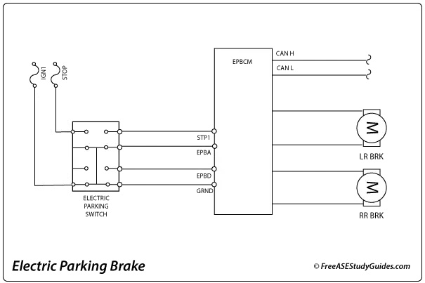
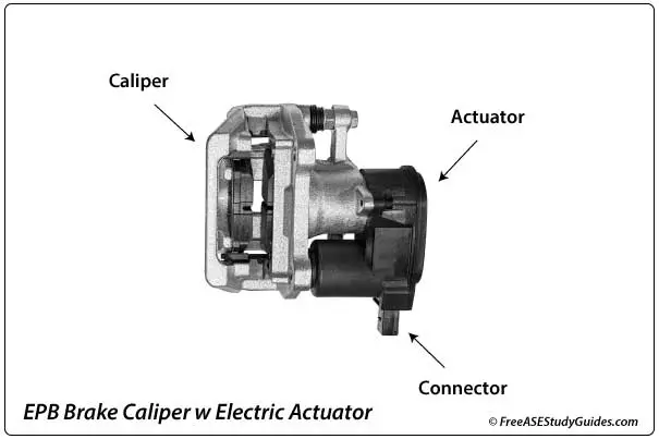
Electric parking brakes have a switch in the passenger compartment. Caliper-integrated EPB parking brakes are typical, have actuators/motors fastened to the brake caliper, and have no cables to adjust. Instead of a brake cable, an electronic control unit receives inputs and operates the electric motors.
The two most common causes for the red brake warning lamp to illuminate on a vehicle with a manual parking brake system are low brake fluid level in the reservoir or a slightly engaged parking brake. In addition to manual parking brakes, the EBCM, fuse/relay, switch, and caliper-mounted brake actuators in electric parking brake systems can fail, resulting in the "service parking brake" warning lamp.