CAN Bus Voltage
The CAN or controller area network is a serial priority-based messaging protocol invented by Bosch. It has proven reliable and the industry standard for high-speed automotive network communications.
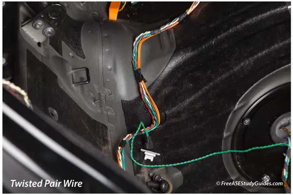
The twisted pair wire used on the CAN bus allows electromagnetic interference to cancel itself out. In addition, differential signaling reduces the effects of noise on the network.
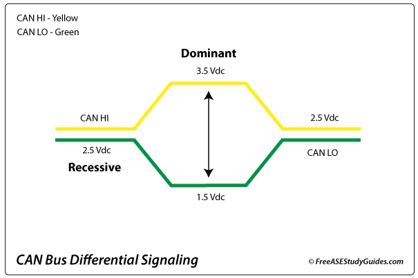
The control modules use differential signaling to send messages over the CAN HI and CAN LO lines. There are two levels: dominant and recessive. In a recessive state, the voltage on both lines remains at around 2.5 Vdc. In the dominant state, the voltage on the CAN HI increases while the voltage on the CAN LO decreases.
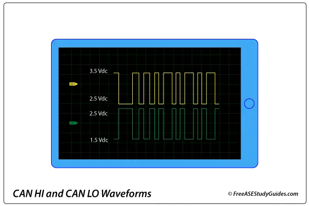
The voltage pattern displayed on the oscilloscope above represents activity on the bus. Notice that the voltage on the CAN HI line increases to around 3.5 Vdc while the voltage on the CAN LO line decreases to about 1.5 Vdc and then returns to 2.5 Vdc. This series of on-and-off or dominant and recessive voltage levels mirror each other and represent a CAN bus message.
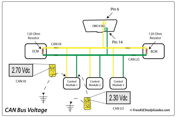
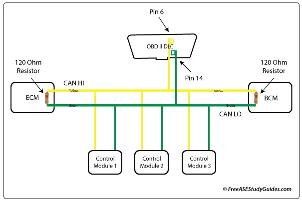
A multimeter can measure the average of all voltage signals on the CAN bus. The reading changes with the activity on the bus. Typically, the measurement is taken from the OBD II DLC of a system without a gateway or by back-probing the CAN HI and CAN LO pins of an easy-to-access control module's connector on a system with a gateway. The signal should be above 2.5 Vdc on the CAN HI wire and below 2.5 Vdc on the CAN LO wire. When CAN HI shorts to CAN LO, the voltage will remain around 2.5 Vdc on both lines.