Brake Light Circuits
Automotive brake light systems use parallel circuits. A parallel circuit differs from a serial circuit because the other bulbs still function normally if one bulb fails. This is not true in a series circuit. If one of the bulbs burns out in a series circuit, the entire circuit is rendered inoperable.
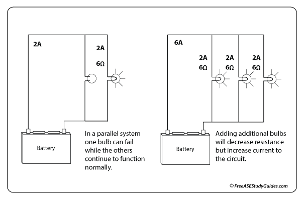
In a parallel circuit, current can flow through more than one branch at a time. If one of the branches fails and creates an open, the energy travels to the next branch. Each bulb in the brake light circuit receives 12 volts regardless of how many bulbs are added.
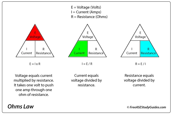
Each item added to a parallel circuit decreases resistance, increasing current; current flows through all bulbs regardless of resistance. Remember Ohm's Law, Voltage (E) = Current (I) x Restance (R), whenever working with electrical circuits. Use the formulas in the chart above; providing any two values calculates the third. To solve for resistance, R=E/I, divide the voltage by the current.
Always be careful and check specifications before adding additional items to a factory system. Adding more items lowers resistance but increases current (amperage) in the circuit and can damage components and wiring.