Manual Transmission Synchronizers
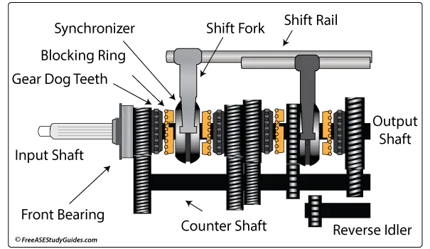
Many of today's cars and light trucks use synchromesh synchronized manual transmissions. They contain an input shaft, an output shaft, and a countershaft. The output shaft fits and spins in a bore in the center of the input shaft. The input shaft contains a pinion gear in constant mesh with the countershaft. The gears on the countershaft are fixed, while the gears on the output shaft spin freely on the shaft. The input and output shafts combined are considered the main shaft.
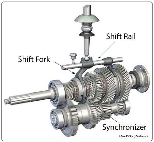
They're designed to provide smooth shifting and transition between gears. The synchronizer has a hub, sleeve, springs, and insert keys. The hub is splined to the main shaft, and the sleeve is splined to the hub. Spring-loaded inserts keep the sleeve centered on the hub. These inserts move with the sleeve as the shift fork moves the sleeve toward the gear.
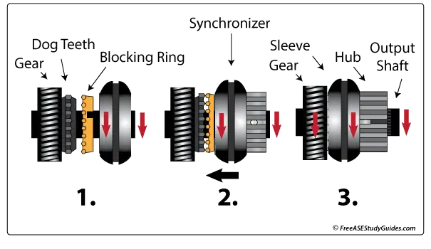
(1) The blocking ring rides between the synchronizer and the gear. (2) As the shift fork moves the sleeve toward the gear, the blocking ring is also moved and contacts the gear first. The ring has fine grooves or friction material on its inner cone that grip the gear and bring it to the same speed as the output shaft. It's made of a soft brass or copper material and has pointed teeth that align the sleeve with the dog teeth on the gear. (3) This brings the shaft and the gear to the same speed, making it easy for the synchronizer sleeve to slide over and lock the gear to the shaft. This produces the desired gear ratio.